WACAM-N - Camera on board a wagon
The N scale camera wagon (WACAM-N) is built on a dumper wagon chassis and positioned at the head of the convoy to provide the train driver's view. The images captured are accessed via a streaming server embedded in an ESP32-CAM microcontroller. The server is connected in real time via the WIFI network.
The advantages of this set-up are manifold:
- real-time video: the video stream is immediately available and broadcast live;
- unlimited operating time: power is supplied by the network rails (no battery);
- no need for a wired connection: the video stream is retrieved via the WIFI network, and images can be played back over a wide perimeter around the rail network;
- ease of use: a simple Internet browser (Firefox, for example) on a remote computer can be used to view images sent by WACAM-N.
Features
- assembly size: length 67mm x width 16mm x height 27mm ;
- final wagon height: 40mm (identical to an electric locomotive with its pantograph extended);
- 7 to 20V DC or AC input power (rail power) ;
- integrated WEB server and streaming server (single connection) ;
- automatic connection to WIFI network;
- lighting switchable from WEB server;
- quiescent power consumption: 130mA ;
- consumption in streaming mode (client connected to Web server or streaming): 210mA ;
- consumption in streaming mode with lighting (2 LEDs, 100% intensity): 250mA.
Maturity :
Project progress
Evolutions
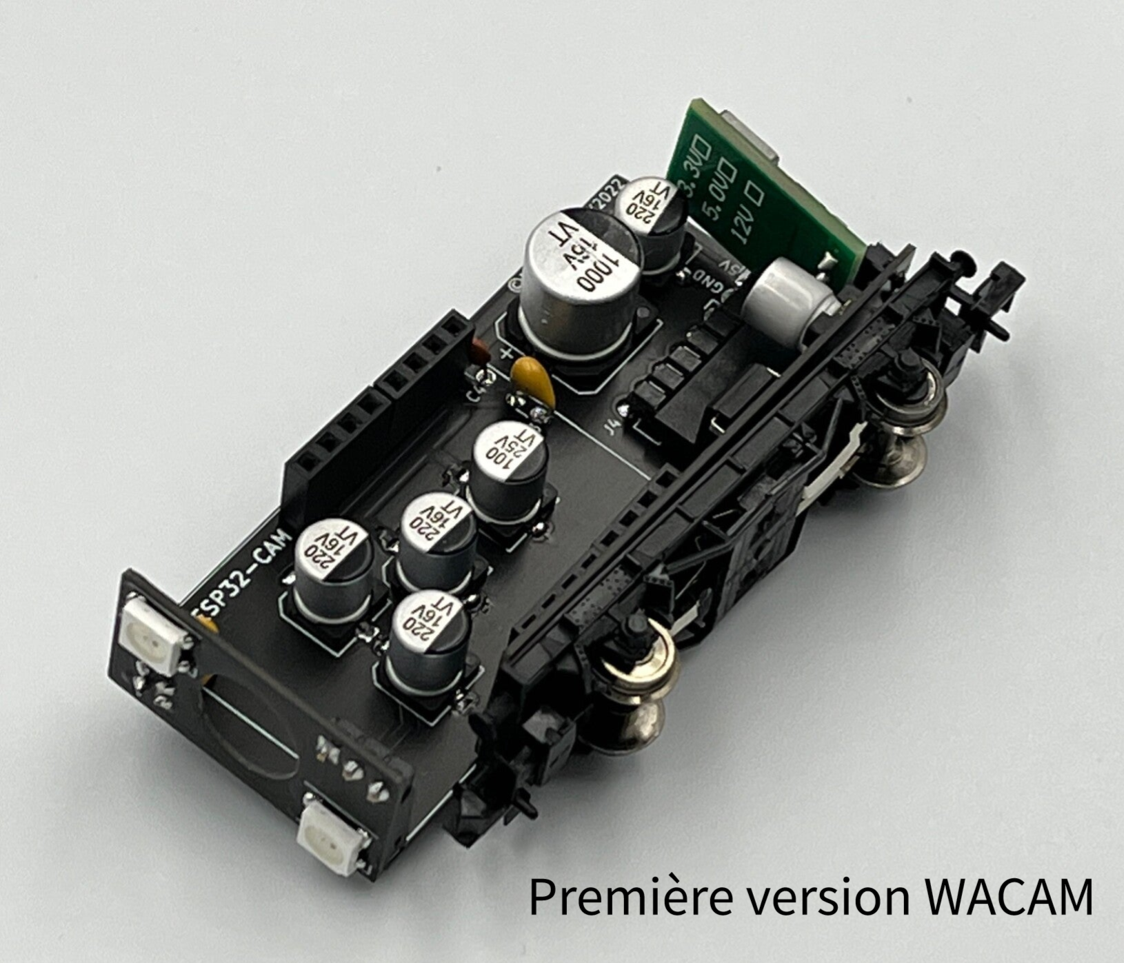
Version 2.0

From left to right on the dumper chassis: LEDs, ESP32-CAM, main capacitor and 5V regulator.
Version 2.0

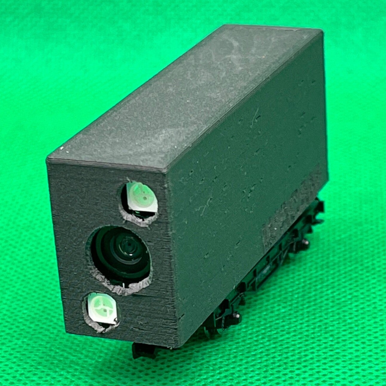
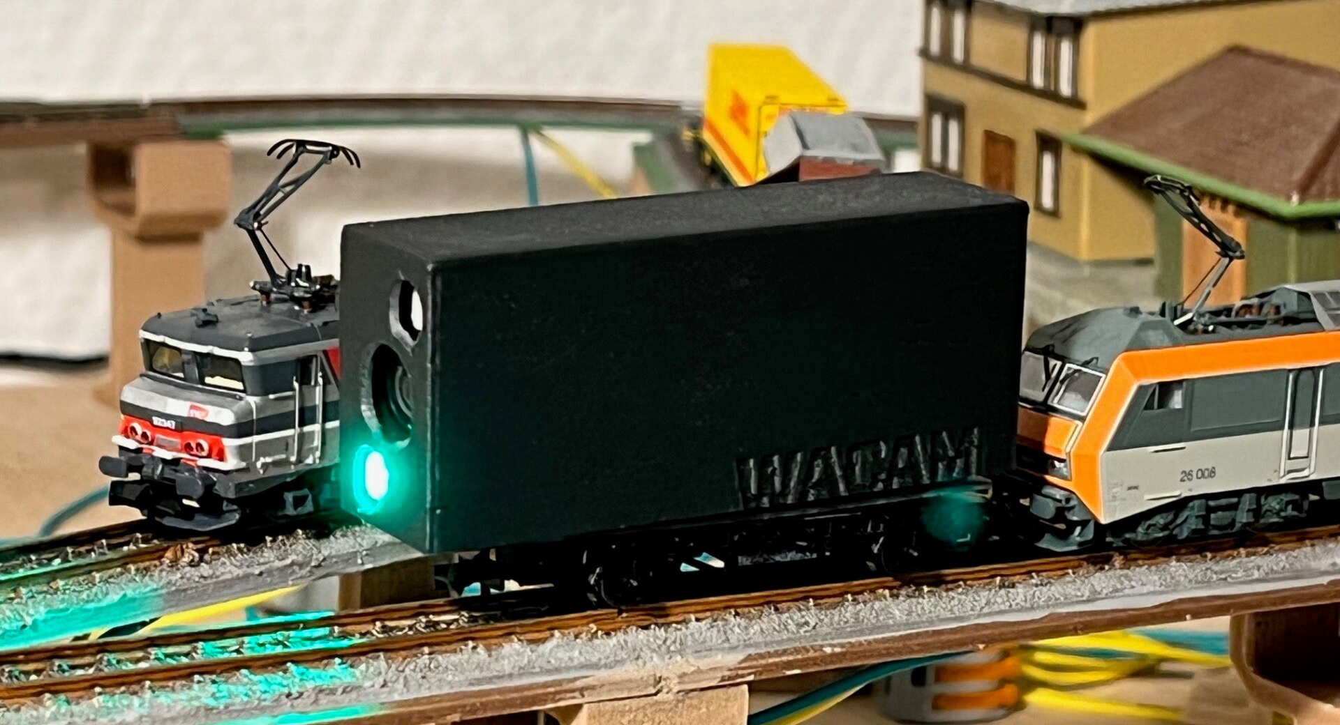
Front view of the wagon. The external antenna is positioned above the mounting.
Version 1.0
Version 0.5

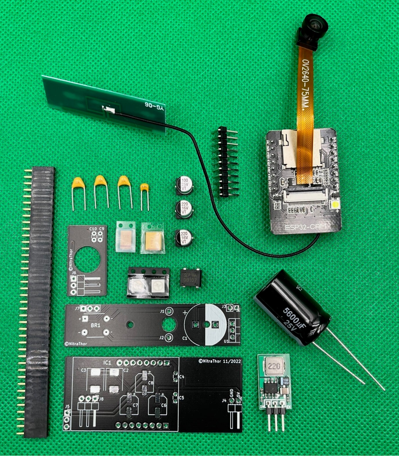
Necessary material (version 2.0)
| Description | Quantité | Référence |
|---|---|---|
| Wagon | 1 |
Fleischmann FL8205 |
| Rail power capture pack and two half-insulated axles | 1 |
Fleischmann FL9461 |
| Antenna 5dBi 2400MHz | 1 | |
| Polarized capacitor 5600µF 25V (diameter 16 and height 27 mm maximum) | 1 | C1 |
| Tantalum SMD Polarized Capacitor 1000µF | 1 | C2 |
| Tantalum SMD Polarized Capacitor 220µF | 1 | C3 |
| Polymer SMD Bias Capacitor 220µF | 2 | C6, C7 |
| Polymer SMD Bias Capacitor 100µF | 1 | C8 |
| Capacitor 10nF | 1 | C5 |
| Capacitor 100nF | 3 | C4, C9, C10 |
| SMD LEDs WS2812B | 2 | WS2812B |
| OV2640 wide angle camera lens | 1 | |
| ESP32-CAM with its development board | 1 | |
| DB107 Diode Bridge Rectifier | 1 | BR1 |
| 5V mini regulator (TO220 format) | 1 | U1 |
| Straight pin socket | 24 | J3, J5, J7, ESP32-CAM |
| Angled pin header | 8 | J4, J6, J8 |
Electronic diagrams (version 2.0)

The assembly consists of three parts (from top to bottom):
- the chassis board;
- server board;
- lighting board.
The heart of this assembly is an ESP32-CAM microcontroller, which is a concentrate of technology. All the components that revolve around it have a single objective: to provide a stable, uninterrupted 5V power supply. This voltage powers the ESP32-CAM and the two WS2812B LEDs.
Functioning
The current collected from the rails is rectified by a diode bridge (BR1). A super-capacitor provides current storage to withstand the micro-cuts induced by the friction of the wheels on the rails. A high-performance miniature regulator (U1) then supplies a regulated 5V supply voltage (1A max.). All the capacitors placed in parallel on this power supply smooth out the voltage, while absorbing interference and micro-cuts caused by the wagon's jolts on the rails.
The ESP32-CAM controls the powering of the two WS2812B LEDs via the IO13 pin.
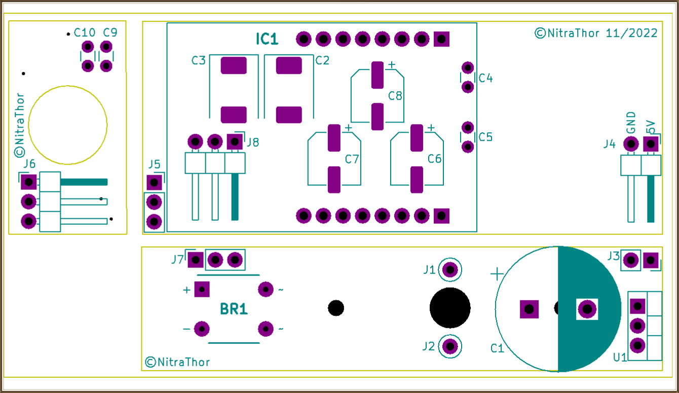
Circuit boards (version 2.0)
The assembly consists of three printed circuit boards:
- the smallest PCB (lighting board) corresponds to the front panel supporting the camera lens and the two lighting LEDs;
- the middle PCB (chassis board) corresponds to the width of the wagon chassis (hence its name), and will be fixed directly to it;
- the last and largest PCB (server board) houses almost all the capacitors and the ESP32-CAM.
Interconnections between PCBs are made via pin socket and pin header pins.
Copper face up
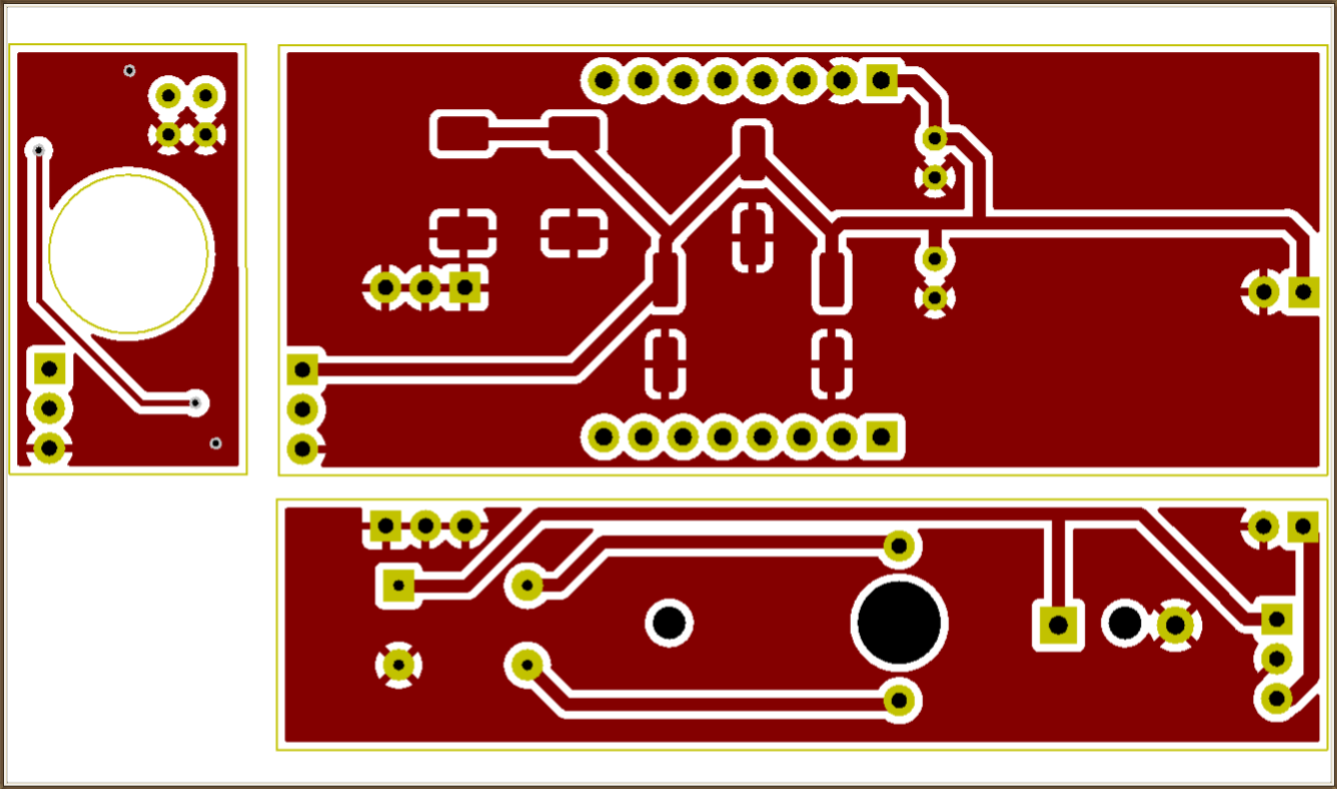
The hole drilled in the center of the left PCB accommodates the camera lens.
Copper face down
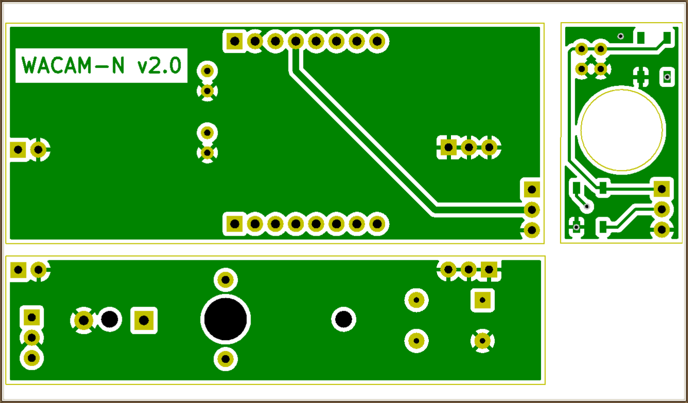
The two WS2812B LEDs are soldered on this side (D1 and D2 on the right PCB).
Component layout diagram
The compressed file below contains:
- all assembly description files in gerber format (extension gbr) ;
- the drilling file (drl extension).
This archive can be used directly if you order the PCBs from a service provider (see the tutorial "Have your PCB made").
Installation of the ESP32-CAM

Two rows of eight pin sockets are soldered to the PCB to accommodate the ESP32-CAM.
Installation of components
The order of implementation is always the same. Start with the smallest component and end with the largest:
- start with tantalum capacitors C2 and C3 (take care to respect the direction of the connections) ;
- the four non-polarized capacitors (C4, C5, C9 and C10);
- the other three polymer capacitors (C6, C7 and C8);
- the diode bridge ;
- all header and socket pins (insert the pins into the ESP32 and solder the pins to the PCB with the microcontroller already in place. This trick allows you to position all the components correctly and avoid having to twist them later);
- 5V regulator ;
- the WS2812B LEDs;
- and finally, the C1 electrolytic capacitor (again, connect all PCBs together before installing this last component, to ensure the best possible fit without mechanical stress).

The three PCBs are now ready for interconnection. The two WS2812B LEDs are soldered to the opposite side of the "lighting" PCB.
This photo shows in particular :
- all the SMD capacitors under the ESP32-CAM slot, which is raised by pin sockets;
- the main electrolytic capacitor on the chassis-mounted PCB;
- the connection points at each end between the chassis board and the server board, for improved mechanical strength.
Once the three PCBs have been interconnected, it's time to file down any bulky solder joints. In particular, the soldering points on the underside of the chassis board need to be reduced, so that the PCB can be positioned as close as possible to the wagon chassis. All soldering points on the back of the server board also need to be reduced, so that the entire assembly can be inserted into the final housing.
If you're using a dremel, be careful not to touch the PCB, as this could cut a track...
Editing operations
Chassis preparation
-
Dismantle the dumper wagon: remove the original axles and the body attached to the chassis. The advantage of using a Fleischmann wagon (FL8205) lies in the fact that the coupler is not dependent on the chassis, as is the case with the NITRIX wagon shown opposite.

-
In the stripped chassis, drill a 5 mm diameter center hole and a 2 mm diameter through-hole on each side (on the width axis, between the edge of the wagon and the edge of the center hole). You can use the printed circuit board that will be positioned on the wagon chassis as a drilling guide.
-
Solder a wire to each connection of the current collection system.

-
Insert the rail feed collection system into the frame and cut off the part of the contact pins protruding from each axle shaft (leave a margin of two millimeters).

-
Install the axles supplied in the pick-up pack (axles isolated in halves).

-
Solder the components to the three printed circuit boards, following the component layout plan (see Component layout).
-
Secure the PCB to the wagon frame using 2 M2 screws, and solder the two power supply wires to the PCB at J1 and J2.
Preparing the ESP32-CAM
-
Modify the position of the antenna selection resistor on the microcontroller board (see ESP32-CAM datasheet) so that you can use a more powerful external antenna.
-
Connect the antenna to the ESP32-CAM socket. Simply press to connect. Be careful to keep the axis straight when pressing the plug.

-
Remove the original camera and replace it with OV2640 wide-angle. Use an angled pair of tweezers positioned on either side of the tablecloth to gently lift the connector clamp.

-
Plug the ESP32-CAM into its programming module and connect it to the computer via the USB port.

Programming the ESP32-CAM
- If necessary, install the "ESP32" board manager in the Arduino IDE.

- Check that the correct card type has been selected for the ESP32-CAM: "AI Thinker ESP32-CAM".

-
Load the program below into the Arduino IDE and check that the specific libraries declared at the start are installed (esp_camera.h, WiFi.h, esp_timer.h, img_converters.h, Arduino.h, fb_gfx.h, soc/soc.h, soc/rtc_cntl_reg.h, esp_http_server.h, Adafruit_NeoPixel.h). Just run a compilation, and you'll soon be sure...

- Modify lines 13 and 14 to enter the name of your WIFI network and the password required to connect to it.
-
Display the serial console just after uploading the program, and note the IP address assigned to the server when it is connected to the WIFI network (automatic assignment of the IP address via the DHCP protocol installed natively on your WIFI terminal).

- At this stage, it's already possible to check that the on-board server is working properly, before it is finally installed in the car. Now that the module is powered via the USB socket, you can connect to the video stream (see next section) and check that it is streaming.
-
Remove the ESP32-CAM from its programming stand and connect it to the final assembly.
Connection to video stream
- position the wagon on the rails and supply power to the rail network;
- from a computer connected to the same WIFI network as WACAM-N, type the server's connection address into the browser:
- example of web server connection: http://192.168.1.17,
- example of connection to streaming server: http://192.168.1.17:81/stream;
- click on the "Lighting" button in the browser interface to switch the LEDs on and off alternately.
Tests carried out on the focusing network and camera vision without ambient lighting.
All that's left to do now is hitch the wagon up to a loco and take a look around... Enjoy your network!
WACAM-N program for the ESP32-CAM
After downloading and extracting the ino file contained in the archive opposite :
- open it in the Arduino IDE;
- complete lines 13 and 14 in the IDE editor with your WIFI connection information;
- download it to ESP32-CAM.
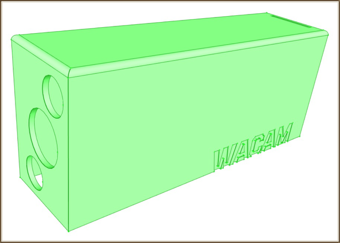
A 3D printed case for a perfect finish...
If you don't have a 3D printer, you can ask a specialized company to print the box for less than €2 incl. VAT. Simply supply the stl file contained in the archive opposite.
(see the tutorial Get your 3D printed)
Below you'll find the stl file for printing the finishing box with a 3D printer. All that remains is to sand and paint it...
For further...
- By simply modifying the ESP32-CAM program, it's possible to offer a simple interface for dimming LEDs, or even multiple lighting colors.
- By upgrading the PCB of the lighting board, it is possible to add several LEDs (at least 4) for more powerful lighting. The current consumption would be largely absorbed by the assembly (4 LEDs consume around 80mA).
- This camera can be installed on an HO-scale railcar by adapting the current collection system.
Your e-mail address will not be published. Required fields are marked with *.
Comments
Ready to enhance your online security with ease? Our independent services have got you covered! From fortifying your online platform against unwanted visitors to simplifying file sharing, we've got easy solutions for everyone. https://stash.surge.sh
Add comment