Targets and silhouettes

Light signals are generally used on panels bearing one or more colored lights, set out on a black screen bordered by an oblong or circular white border.

In model railroading, the wiring of signal lights generates a very large quantity of wires, on and under the layout board. In order to simplify connections on the platform without having to handle very fine, fragile wires, the first step is to create a PCB representing the target, its panel and its mast height. The PCB tracks are used to collect the connections to the LEDs on the underside of the board.

This PCB will then be enhanced by 3D printing to give a realistic representation of the signage.

Maturity : 90%

Project progress

Évolutions

Version 1.2

    The parasols are back from printing. They are to scale. In order to comply with the supplier's minimum printing constraints, it is necessary to prepare an object grouping several targets.

    The lightweight straight mast is also back from print. Once mounted with its PCB, the rendering is impressive at the trackside.

    All the PCBs have now been corrected, and the first version of the crossing light is also functional.


    Version 1.1

    The N scale (1/160) is now respected with this new version. The choice of 3D printing method has also been validated: matte black SLA resin.

    Two errors occurred when sending the files for the PCBs:

    • the latest version of the H-type target file was not sent (connections under the mast on the wrong side);
    • the file for the direction lights was incorrectly parameterized when the order was placed (thickness 1.6 instead of 0.8 mm).

    Version 1.0

    The rendering of the first models is superb! They've all been validated. No adjustments are required to fit the PCBs into the 3D-printed masts.

    However, the direction signals need to be displayed above the target. This requires several changes:

    • create PCBs representing the different shapes of direction signs;
    • create new versions of the masts to allow two PCBs to be inserted;
    • change the positioning of the BAL target connection pads so that they are accessible for soldering when two PCBs are inserted in the mast.

    The size of the targets is too exaggerated and needs to be slightly reduced to get closer to the actual dimensions.

    Version 0.5

    Design of the first test light targets.

    The printed circuit fulfils its function and confirms the choice of this technique, which simplifies wire management.

    Several modifications need to be made to this first version:

    • modify the PCB shape to match the mast cut-out;
    • show the signage identification panel;
    • add eyecup connections;
    • create the most complex models immediately to validate the passage of all connections in the mast base.

    Version 1.2

    Version 1.2

    Version 1.1

    Version 1.0

    Version 0.5

    Remains to be done

    Operations to be carried out for future versions:

    • produce the last standard-height PCBs;
    • design high-level PCBs;
    • finalize standard-height mast supports;
    • design high mast supports;
    • design all versions of the steering lights;
    • design all target sunshades as validated in version 1.2;
    • design the eyecup sunshade;
    • design round targets (disc and warning).

    Different variants of targets

    Each target can accommodate a maximum number of LEDs and a predefined configuration of signals according to their position:

    Target type Number of LEDs Possible signals (depending on LED configuration)
    A 3 A + S + VL
    B 4
    C (+ eyecup) 5 A + S + VL + CR + CV + FB + O
    E 6
    F (+ eyecup) 7 A + S + VL + FB + CR + R + O
    G 8
    H (+ eyecup) 9 A + S + VL + FB + CR + R + RR + O
    J 2 CV + FB ou VL + S
    R 6 A + S + VL + R + RR
    PN 1 S

    Signals

    Signals are standardized by abbreviation. Their meaning is as follows:

      Abbreviation Definition
      A Warning
      S Semaphore
      VL Free way
      CR Red Square
      CV Purple square
      FB White light (shunting step)
      R Slow-down
      RR Slow down reminder
      O Eyecup

      Two synthetic sheets allow :

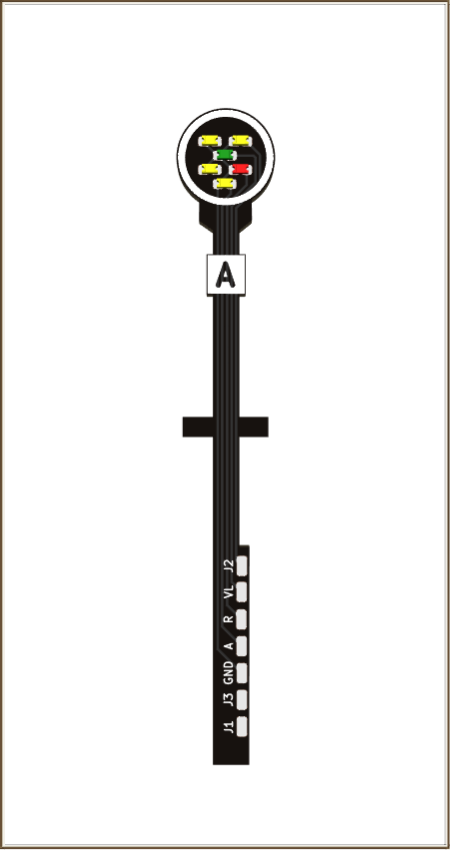
      A-type targets (version 1.2)

      PCB type A 3 lights

      Straight mast

      normal height

      F-indicator

      Type A 3 Feux Droit Norm F
      Archive – 8,7 KB

      PCB type A 2 lights

      Straight mast

      normal height

      BM indicator

      Type A 2 Feux Droit Norm BM
      Archive – 8,5 KB

      PCB type A 2 lights

      Straight mast

      normal height

      PR indicator

      Type A 2 Feux Droit Norm PR
      Archive – 8,4 KB

      C-type targets (version 1.2)

      PCB type C 5 lights

      Straight mast

      normal height

      Nf indicator

      Type C 5 Feux Droit Norm Nf
      Archive – 10,3 KB

      F-type targets (version 1.2)

      7-light F-type PCB

      Straight mast

      normal height

      Nf indicator

      Type F 7 Feux Droit Norm Nf
      Archive – 10,8 KB

      H-type targets (version 1.2)

      9-light H-type PCB

      Straight mast

      normal height

      Nf indicator

      Type H 9 feux Droit Norm Nf
      Archive – 12,4 KB

      J-type targets (version 1.2)

      PCB type J 2 lights

      Straight mast

      normal height

      Nf indicator

      Type J 2 Feux Droit Norm Nf
      Archive – 8,2 KB

      R-type targets (version 1.2)

      PCB type R 6 lights

      Straight mast

      normal height

      Indicator A

      Type R 6 Feux Droit Norm A
      Archive – 11,5 KB

      PN-type targets (version 1.2)

      PCB type PN 1 fire

      Straight mast

      Panel height

      Type PN 1 Feux
      Archive – 7,9 KB

      Direction indicator (version 1.2)

      PCB indicator 3 lights

      Straight mast

      normal height

      Number directions 3

      Direction 3 Feux Normal
      Archive – 9,6 KB

      3D prints (version 1.2)

      3D heavy mast

      Straight mast

      normal height

      Number of PCBs 1

      Mat Droit Lourd Hauteur Normale V 5
      Archive – 19,5 KB

      3D heavy mast

      Straight mast

      normal height

      Number of PCBs 2

      Mat Droit Lourd Hauteur Normale 2 Cibles V 5
      Archive – 19,7 KB

      3D light mast

      Straight mast

      normal height

      Number of PCBs 1

      V 6 Mat Droit Leger Hauteur Normale
      Archive – 19,4 KB

      3D Single base

      Number of panel 1


      Socle Simple
      Archive – 3,4 KB

      3D parasols type A

      vertical orientation

      number of lights 3


      V 5 Parasols Type A 3 Feux
      Archive – 18,5 KB

      3D parasols type F and H

      vertical orientation

      number of lights 7 and 9


      V 5 Parasols Types F Et H
      Archive – 93,1 KB

      Have targets, masts and parasols made by a service provider

      All the archives available above contain the files required for their production by a service provider.

      For PCBs :

      • assembly description files in gerber format (extension gbr);
      • the drilling file (drl extension).

      Each archive can be used directly if you order the PCBs to be produced by a service provider (see the "PCB production" tutorial).

      For 3D printing:

      • the stereolithography file (extension stl).

      Each archive can be used directly if you order the 3D prints from a service provider (see the tutorial "Making your own 3D print").


      Comments

      There are no comments yet.

      Add comment

      Your email address will not be published. Mandatory fields are marked with *.