CDC - Canton presence detection card
This interface card, which can be used with the common zone control module (MOC), allows the detection of DCC current consumption on two separate blocks. A MOC equipped with this card on all its locations, allows the detection of the presence of 16 different blocks. Just connect each canton to the board with a wire. DCC signal and current consumption detection are supported by the interface.
CDC Card Features
The characteristics of this interface card are :
- PCB dimensions L 60 x W 25 mm ;
- 5V DC power supply from MOC ;
- Optical isolation between the DCC current and the circuits connected to the MOC ;
- Detection of connection to the MOC by a resistance of 1Kohms ;
- DCC current flows even if the MOC powering the board is turned off.
CDC interface board connections

Maturity :
Interface board progress
Version 1.3
The CDC interface board is completely finalized and all anomalies are corrected in this release.

Necessary material (version 1.3)
| Description | Quantity | PCB reference |
|---|---|---|
| Resistor 220 ohms | 2 | R1, R2 |
| Resistor 1K | 1 | R3 |
| Capacitor 10µF | 2 | C1, C2 |
| 6-pin IC socket | 2 | U1, U2 |
| Opto coupler 4N35 | 2 | U1, U2 |
| Diode 1N4001 | 8 | D1 à D8 |
| Right pin header | 7 | J1, J3 |
| 2-pin screw terminal block | 1 | J2 |
The interface board sense resistor (R3) should have a tolerance of =/- 2%. This resistance must be precise so that the detection by the MOC is carried out without any possible error of interpretation.
Electronic diagram (version 1.3)

Functioning
As soon as a DCC current is consumed on one of the two sections connected to the interface card, the potential appearing on the corresponding diodes makes it possible to trigger the opto-coupler. The diodes are mounted two by two head to tail so as to cover the two half-periods of the DCC signal. The 120 ohm resistor makes it possible to limit the current flowing in the opto-coupler.
Once the opto-coupler has been triggered, it charges a signal stabilization capacitor (C1 for the first section and C2 for the second) which gives the consumption information to the MOC via connector J1.
Resistor R3, also connected to J1, corresponds to the interface card's detection resistor. Each type of interface card has a different resistor value so that it can be recognized by the MOC.
Printed circuit board (version 1.3)
- The printed circuit has a ground plane on each side of the circuit in order to attenuate interference as much as possible.
- The two fixing holes on the side of the pin header pins make it possible to secure the interface card with the MOC module which will house it and thus, not to exert any force on these pins during the connection / disconnection operations of the blocks.
Copper face up

Copper face down

Component layout diagram

Realization of the printed circuit
The zip file below contains :
- All assembly description files in gerber format (gbr extension) ;
- The drilling file (extension drl).
This compressed file can be used directly if you order the production of printed circuits from a service provider (see the tutorial "Have your PCB made").
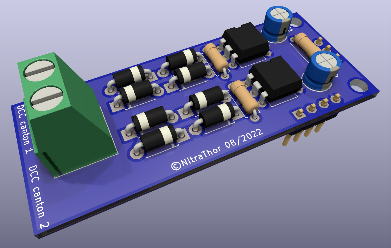
3D view of the CDC map
Installation of components

Placing the components on the board does not pose any particular problem.
The order of implementation is always the same. We start with the smallest component and end with the largest :
- Start with the eight diodes ;
- The three resistors ;
- The two opto-coupler supports ;
- The J1 and J3 connection pins which are soldered on the underside ;
- Both polarized capacitor ;
- Finish with the connection terminal block to the rails.
As this map will be used to follow the occupation of the cantons, all that remains is to make a series of them... To your soldering irons!
Your email address will not be published. Mandatory fields are marked with *.
Comments
Add comment