Minimum DCC micro control unit

This DCC microcontroller enables complete operation of a digital rail network. Combined with a computer running JMRI software, it transforms commands sent by the network controller (computer + JMRI software) into DCC frames. The micro central unit is connected to the controller via a USB cable, and to the network rails for which it supplies the power signal.
With the NMRA-compliant DCC++ program, all digitalized motrices can be controlled on any scale (HO, N...). The proposed solution not only enables several locomotives to be controlled simultaneously, but also the management of accessories (points, signals, etc.) via the DCC protocol.
Features
- compact mounting dimensions (64 x 64 x 50 mm) ;
- locomotive addressing in short or long addresses;
- speed in 128 steps;
- simultaneous control of several locomotives (direction, speed and 29 functions);
- control of over 2000 accessories via DCC protocol;
- maximum power supply 4A ;
- short-circuit protection (DCC power cut-off in the event of over-consumption, to prevent damage to electronics and rolling stock);
- CV programming mode selector for one locomotive ;
- isolation of the programming section from the rest of the network while a locomotive's decoder is being set;
- emergency stop punch.

This project describes all the steps involved in creating a rail network using this micro power plant:
- assembly of the electronic circuit;
- programming the Arduino Nano microcontroller;
- functional testing ;
- installation of JMRI software;
- locomotive parameterization;
- rail network operation (traction and functions from the controller).
The DCC micro control unit alone provides the interface between the computer and all the decoders available on the rails of the rail network (locomotives, points, signals, etc.). Each locomotive can therefore be individually controlled by the DCC signal sent to the rails.
Maturity :
Project status
Évolutions
Version 1.3

Version 1.2

Version 1.0

Version 0.5

Prerequisites
So, with this one little setup, you can create your first digital network (DCC). However, there are a few pre-requisites you'll need before you can begin. In addition to a soldering iron and the small equipment that goes with it, you'll need:
- a computer (laptop or desktop, close to the network to be controlled, thanks to the USB cable connection);
- one or more digital locomotives (digital) with or without sound functions;
- a USB cable for connection to the Arduino Nano microcontroller board (several USB connector sizes are available);
- a 15 or 18V DC power supply (depending on the scale selected) capable of delivering a current of over 4A.
Electronic schematic (version 1.3)

The heart of this assembly is an Arduino Nano v3 board into which the DCC++ program (adapted to the characteristics of this circuit) has been uploaded.
Commands are sent to the microcontroller via the serial link (USB) from a computer running the free JMRI software.
The DCC signal generated by the Nano board passes through a power circuit before being sent to the rails to control the locomotive decoders and the various DCC accessories.
Hardware requirements (version 1.3)
| Description | Quantity | Reference | Url de recherche |
|---|---|---|---|
| Tantalum polarized capacitor 1µF | 1 | C1 | condensateur + tantale + traversant + 1µF |
| Capacitor 100nF | 3 | C2, C4, C5 | condensateur + céramique + traversant + 100nF |
| Polarized electrolytic capacitor 220µF | 1 | C3 | condensateur + polarisé + électrolytique + radial + traversant+ 220µF + 25V |
| Diode 1N4001 | 4 | D1, D2, D3, D4 | diode + 1N4001 + 50V + 1A |
| 3mm two-color LED (green and red), common cathode | 1 | D9 | led + 3mm + rouge + et + rert + cathode + commune |
| LED 3mm yellow | 1 | D10 | led + 3mm + jaune |
| LED 3mm blue | 1 | D11 | led + 3mm + bleue |
| PCB-mounted 15V 5A power supply socket (5.5 x 2.5mm or 5.5 x 2.1mm depending on transformer plug) | 1 | J1 | 694108301002 + Fiche + jack + alimentation + 6.4mm + Angle + droit + Würth + Elektronik |
| Rail power supply socket (3-pin, 3.8mm pitch, right-angle for PCB mounting) | 1 | J2 | |
| Pin header jumper (pitch 2.54): short-circuit with a jumper to avoid using the ammeter. | 2 | J3 | |
| NPN transistor PN2222A | 1 | Q1 | |
| Resistance 0.1 Ohm (2 W) | 1 | R1 | |
| 1K resistor (1/4 W) | 3 | R2, R6, R7 | |
| 10K resistor (1/4 W) | 1 | R3 | |
| 2K resistor (1/4 W) | 2 | R4, R5 | |
| Emergency stop push-button (diameter 16mm) | 1 | SW1 | |
| 4RT switch for mode selection (operation / programming) | 1 | SW2, SW3 | |
| Arduino Nano v3 | 1 | U1 | |
| Double pont en H L298N | 1 | U2 | |
| TO-220 aluminium heat sink 25 x 23 x 16mm with two fixing pins | 1 | Fixation U2 | Dissipateur + to220 + l298n + 25mm + 23mm + 16mm |
| Dual amp OP LM358 | 1 | U3 | |
| Straight pin socket (pitch 2.54) | 30 | ||
| Straight Pin Header (pitch 2.54) | 21 | ||
| 8-pin bracket (LM358) | 1 | Fixation U3 | |
| Optional: analog ammeter to display the instantaneous current consumption of the assembly | 1 | MES1 | |
| Transformer 220 /15V 5A (75W) | 1 | Adaptateur + Secteur + 15V + 5A + 75W | |
| USB type A to mini B - 5-pin cable | 1 | Câble + USB + 2.0 + Type + A + vers + Mini + B + 5 + Broches + Pin + Mâle + 30cm + Compatible + Arduino + Nano |
How it works
5 V power supply

This DCC microcontroller is supplied with 5V via the USB link between the computer and the Arduino Nano board. As the 5V current consumption for this assembly is only a few tens of milliamperes (Arduino Nano, L298N logic and two LEDs), the computer is more than capable of supplying this voltage to the assembly, thus avoiding the need for a voltage step-down converter.
3D view of the DCC microcontroller's main board, on which all electronic components and connection connectors are located.
DCC signal generation
The Arduino Nano's ATmega328 microcontroller, embedding an adaptation of the DCC++ program, retrieves commands in text format via the serial link and transforms them into a DCC signal. When no commands are to be sent, the DCC++ software generates dummy frames (empty or idle frames) to keep the power signal on track.

Transistor signal inverter circuit:
-
a high level of the original signal activates the base of the transistor, which becomes conducting => the inverted signal goes low.
-
a low level of the original signal blocks the transistor => a high level appears on the pin of the inverted signal.
All frames generated by the program are output by the microcontroller with an amplitude between 0 and 5V. A signal inverter circuit (Q1, R6 and R7) is used to present both forms of the signal to the H-bridge (U2): the frame output by the microcontroller and the same signal inverted.
Each side of the H-bridge is controlled by one of the two signals (origin and reverse). The L298N power circuit will therefore create a DCC signal by reproducing the input signal by alternately applying the 15 V power supply in one direction, then in the other, thus changing the amplitude from 0 / 5 V (signal generated by the Nano) to -15V / +15 V (power DCC signal applied to the rails):
- 0 V input => -15 V DCC ;
- 5 V input => +15 V DCC.
(See H-bridge operating principle).
The L298N double H-bridge is controlled by the same signal on both bridges. This allows the two outputs to be connected in parallel, thus doubling the power. Each output can absorb a current of 2A, so parallel connection generates a DCC current of up to 4A (peaks of 6A supported by the L298N circuit).
Short-circuit protection
The power circuit is supplied at 15V with a 0.1 ohm shunt resistor in series (R1). Differential voltage measurement across R1 is performed by a circuit (U3, R2, R3 and C1 opposite) around an operational amplifier (AOP), converting the current drawn into voltage, which is presented on pins A0 and A1 of the microcontroller.
When the voltage on these analog pins reaches the threshold set in the software, the consumption monitoring routine stops the generation of the DCC signal, which is indicated by the D9 LED lighting up red. To restart the control unit, the power-up command must be sent again via the serial link, so that D9 turns green (DCC generation).
The emergency stop punch (SW1) connects the Nano's A0 and A1 monitoring pins directly to 5 V, simulating a short-circuit on the rails.

Current consumption measurement circuit built around an operational amplifier which converts the measurement into a proportional voltage.
Assembly calculations
The components around the operational amplifier are mounted as a linear voltage amplifier with negative feedback. In fact, this pompous name simply refers to a linear voltage amplifier. It multiplies the voltage applied to pin 3 by the gain of the circuit and presents the result on pin 1 (output of the op amp).
- Voltage across R1 (U = R * I) = 0.1V per Ampere
- Power dissipated by R1 for 4A (P = U * I) = 0.4V * 4A = 1.6W (normalized to 2W)
- AOP gain = (R3 / R2) + 1 = (10K / 1K) + 1 = 11
- AOP output for 4A = pin 3 voltage * gain = 0.4V * 11 = 4.4V
For a DCC current consumption varying between 0 and 4A on the rails, the voltage at the output of the AOP assembly will vary linearly between 0 and 4.4V. The microcontroller's analog pins measure a voltage that can vary between 0 and 5V (supply voltage). This voltage is converted to an integer on a scale from 0 to 1023 by the microcontroller's analog/digital converter. A voltage of 4.4V therefore corresponds to (1023 * 4.4) / 5 = 900. This is the maximum value that can be set in the program. The maximum current constant, CURRENT_SAMPLE_MAX, must not exceed this value of 900 (see the section on DCC++ constants below).
If, for example, you wish to limit current consumption to 2A, because no more than 7 or 8 locomotives will be used simultaneously (in N scale), the value of the constant will be set to 450. It is preferable to always adjust this value as close as possible to the maximum current consumption, so as to circulate as little current as possible in the event of a short-circuit. If your network grows and requires more current, there's nothing to stop you uploading the DCC++ program to the Arduino Nano board, having set a new maximum current value.
Mode selector
The DCC micro control unit offers a "programming" mode via a selector switch on the front of the assembly (connected to SW2 and SW3 on the printed circuit board). As this circuit has no dedicated programming channel, to save resources, isolation from the rest of the circuit is achieved by using the fourth switch on the selector (SW3) to cut the power supply to the rails around the programming section.

The third pin on the DCC connector is used to disconnect the mains supply while a locomotive is being programmed on the programming section.
Depending on the position of the selector switch on the minimum DCC microcontroller :
- operating mode: both sections are powered normally and all drives are accessible via the DCC protocol;
- programming mode: only the programming section is powered, and the motor on this section can be set without affecting the other decoders on the network.
By supplying the entire network from the end of a siding dedicated to locomotive programming, the DCC microcenter lets you :
- Parameterize a new locomotive placed on the programming section by assigning it an order number. Then, once you've moved the selector to the operating position, you can drive it directly to its destination on the network.
- Control the movement of a power unit from the network to the programming section, then, after changing the selector to the programming position, change the CV settings on its decoder. Then, as before, to be able to use the traction unit again directly on the network in operating mode, without having to manipulate it.

Alternatively, you can position the programming segment in the middle of a track by isolating each end of a rail in this segment. By connecting the third DCC pin of the assembly to the two adjacent segments of the isolated rail, the network will not be impacted during the programming phase.
Current constraints
Many of the power assemblies on offer do not take sufficient account of the aspect of high currents. The risks involved are well known: overheating, damaged components, sparks, flames, fire...
In order to withstand a current of 4 A, the entire power supply chain must be calibrated to withstand this current:
- the 15V supply transformer must be able to deliver a current greater than 4 A;
- the jack plug connected to the PCB must be able to withstand this current without overheating the contacts;
- the PCB tracks must be large enough for this current without acting as a fuse;
- the number of PCB vias must be adapted to the current (minimum 1 via per ampere, recommended 1 via for 500 mA);
- power components switching these currents must be protected by heatsinks;
- the pins and wires of the DCC connector linking the assembly to the rails must have a cross-section capable of withstanding this current.
The most fragile element in this chain (the weakest link...) will determine the maximum current supported by the assembly as a whole. If all the elements of the assembly can withstand 4 A, but your jack socket soldered to the PCB is only rated for 1 A (as is the case with most sockets of this type), your assembly is no longer guaranteed to withstand more than one ampere !
Printed circuit boards (version 1.3)
The assembly consists of two printed circuit boards:
- the main PCB, which supports all DCC microcontroller components;
- the front panel PCB, containing the buttons and LEDs.
The two PCBs are sandwiched together and held together by spacers. Electrical interconnections between the front panel and the main circuit are made using Dupont wires, sacrificed for the good cause...
Copper face up

Copper underside

Component layout diagram

The archive opposite contains the files needed to create the PCB for the DCC microcontroller:
- all assembly description files in gerber format (extension gbr) ;
- the drilling file (drl extension).
This archive can be used directly if you order the PCBs from a service provider (see the tutorial Making your own PCB).
The second archive contains the files needed to create the front panel of the assembly (FAV), which will house the buttons and indicators.
3D view of printed circuit boards
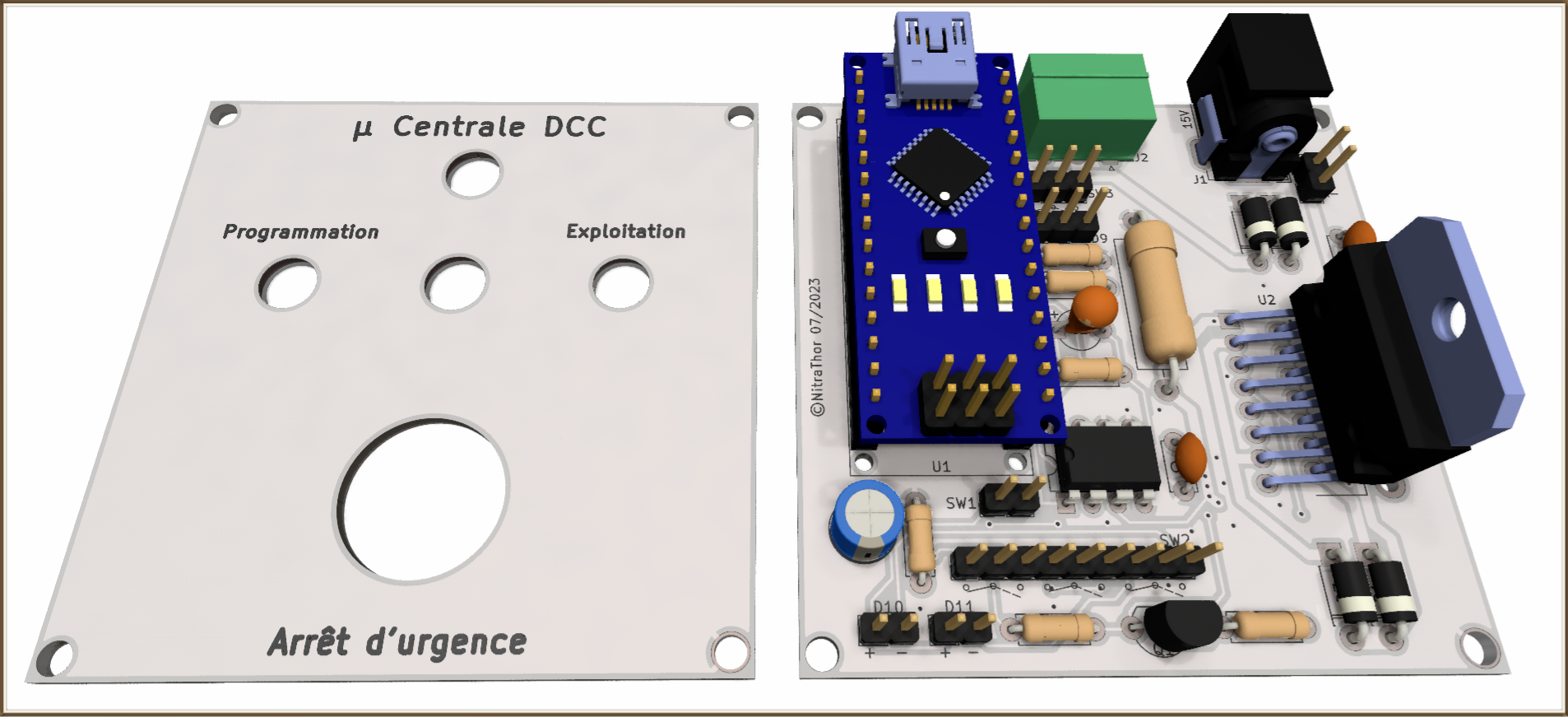
In addition to the project's main PCB, a second printed circuit board (FAV) is used to create the front panel of the assembly, which houses all the LEDs and control buttons. The front panel is screen-printed in French and English (front and back).
Component installation

The order of implementation is always the same. Start with the smallest component and end with the largest:
- 1/4 W resistors ;
- diodes ;
- C2, C4 and C5 capacitors;
- LM358 support ;
- the 18 pin header ;
- Nano's 30 pin sockets (insert the Nano into the pin sockets to
- solder them in place for immediate positioning) ;
- the transistor ;
- polarized tantalum capacitor (pay attention to direction of installation) ;
- electrolytic capacitor (observe polarity);
- the power resistor, which should be raised a few millimeters to avoid contact with the PCB;
- the DCC and jack sockets;
- finish with the L298N, to which the heatsink will be attached before final soldering to the PCB, to optimize thermal contact between the two components and facilitate assembly. You can also insert a thermal film or apply some thermal paste between these two parts to further improve the efficiency of the cooling system.
Assembly operations

Once the main PCB is complete, it's time to mount the front panel. This is made up of several holes to accommodate the DCC microcontroller's buttons and LEDs:
- three slots for 6 mm diameter LED holders;
- a 6.4 mm diameter slot for the mode selection switch;
- 16 mm diameter emergency stop button;
- four M3 holes (one at each corner of the panel) to hold the front panel in place.

A few additional items are required to complete the assembly:
- eight 20 mm spacers, fitted in pairs to raise the front panel;
- four M3 fixing screws to secure the front panel to the spacers;
- four feet to raise the main PCB.

The electrical interconnection between the two levels of the assembly is made using Dupont wires, one end of which is retained for plugging onto the main PCB.
The other end of the wire is cut to length and, after being stripped and tinned, is soldered to the sight glass or switch.
Unprotected areas must be covered with heat-shrink tubing to prevent accidental contact.

The interconnection between the two PCBs is now complete, and the front panel is ready to be attached to the spacers.
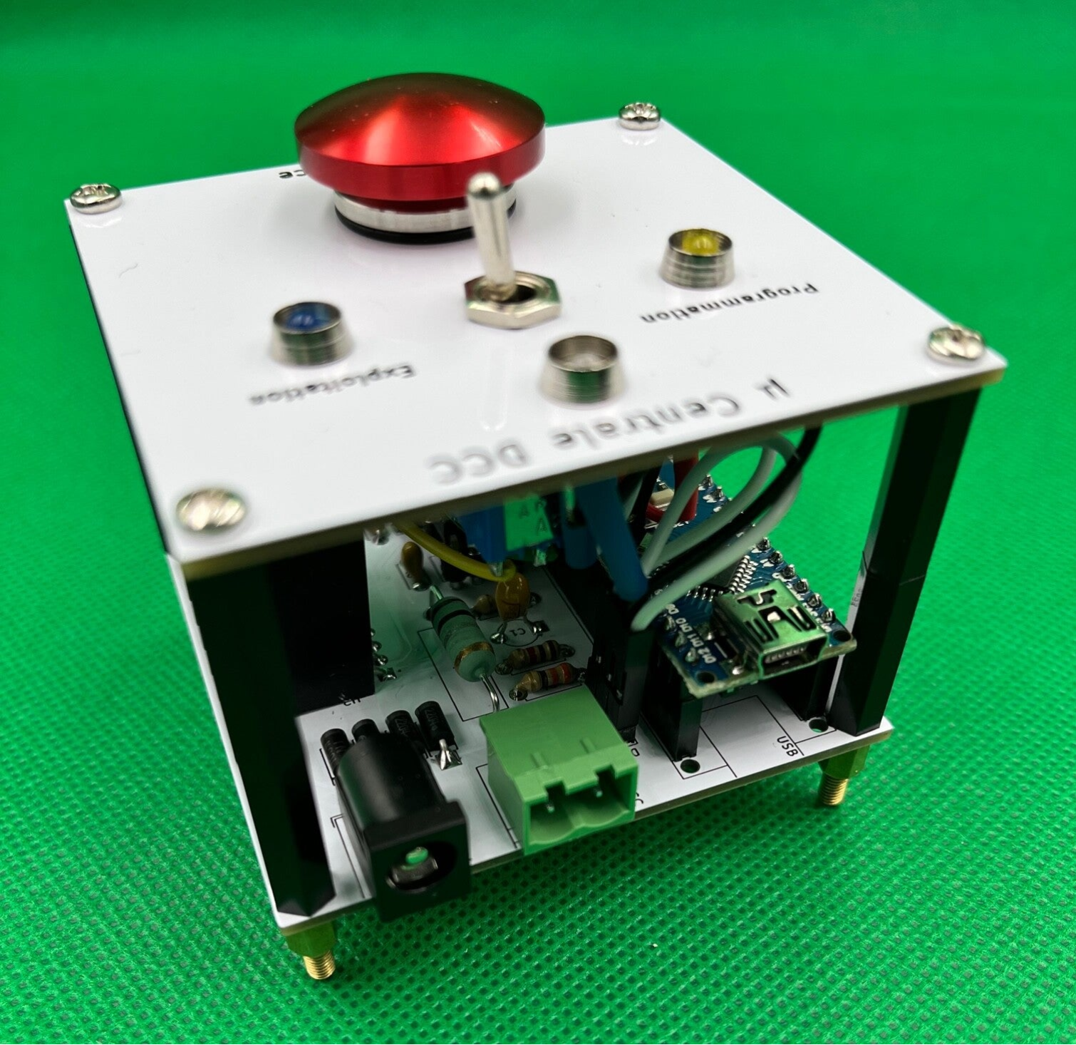
Rear view of the finished assembly. You can see the three connection sockets (from left to right):
- 15 V power jack;
- rail power connector;
- the Nano's USB socket for connection to the computer.
The USB connection to the computer will also be used to update the DCC++ program. It is not necessary to remove the Arduino Nano from the assembly to perform this operation.

To prevent the front panel from generating interference, it can be grounded. The two mounting holes in the bottom right-hand corner of each PCB are surrounded by a pad connected to ground. It is therefore possible to connect the two planes by a simple wire soldered to a washer at each end, which will be locked in the spacer assembly.
Software loaded in the microcontroller
The DCC++ program embedded in the ATmega328 microcontroller of the Arduino Nano, the heart of this assembly, is an adaptation of the magnificent open source version developed by Gregg E. Berman. A few minor modifications have been made to adapt it to the microcontroller:
- references to the Arduino Uno have been replaced by those of the Nano;
- the constants described in the following chapter have been adapted to the characteristics of the assembly.
The archive named Micro_DCC_USB_v1-0 corresponds to the DCC++ program with the above adaptations. It is therefore directly usable with this assembly and can be downloaded as is to the microcontroller.
Download and extract the archive files into a dedicated directory, with the same name as the main file (ino), then :
- Open the ino file in the Arduino IDE (all files are loaded in the tabs).
- Connect the Arduino Nano v3 to the computer via the USB port.
- In the Arduino IDE, check that the correct board type has been selected for the Arduino Nano board: "Arduino Nano, ATmega328P (Old Bootloader)".
- Upload the program to the microcontroller.

DCC++ program constants set for micro control unit
The DCC++ program is made up of several files to segment and simplify understanding of the algorithm for the programmer.
Each major function in the program uses constants, which correspond to values used in several places in the code. The constant therefore substitutes a value for a keyword. The association between the name of the constant and its value (#define <constant> <value>) is described only once. Each time this value is used, the programmer replaces it with the name of the constant.
The advantage of describing the constant only once in the file header is that only one modification needs to be made if the value changes. The programmer doesn't have to go through the whole code to modify the number each time it's used, at the risk of forgetting some...
After opening Micro_DCC_USB_v1-0.ino in the Arduino IDE, each file appears in a tab. The constants below are accessible in the file corresponding to the paragraph title. Modifying these values has a major impact on program behavior. They should therefore be modified only if the impact is known.
CurrentMonitor.h
#define CURRENT_SAMPLE_SMOOTHING 0.1
#define CURRENT_SAMPLE_TIME 10
These two parameters define the smoothing and frequency of the current measurement. Each measurement impacts only one tenth of the overall consumption measurement. By modifying smoothing to 1, measurement smoothing will be suppressed. In this case, a short-circuit will be taken into account more quickly, but with the risk that an erroneous measurement will cause the DCC to stop generating.
#define CURRENT_SAMPLE_MAX 300
Short-circuit detection threshold above which the monitoring routine stops generating the DCC signal (approx. 225 per ampere). For 4 A, change this value to 900.
The default value (300) corresponds to approximately 1.3A, enough to start testing with 4 or 5 locomotives.
Config.h
#define MAX_MAIN_REGISTERS 12
Maximum number of registers for repeated commands.
#define COMM_INTERFACE 0
Set command reception via serial interface (USB).
PacketRegister.h
#define ACK_BASE_COUNT 100
#define ACK_SAMPLE_COUNT 500
#define ACK_SAMPLE_SMOOTHING 0.2
#define ACK_SAMPLE_THRESHOLD 5
Parameters related to current measurements during read/write operations on decoder CVs.
These values have been validated after numerous tests on different decoders.
Preparing for the first start-up of the micro central unit
After assembling the main circuit:
- visually check that all your soldering is complete and clean (no omissions or dry soldering);
- check that the components mounted on the support (Arduino Nano and LM358) are correctly positioned;
- clean the solder joints on the underside with pure isopropyl alcohol to dissolve any traces of resin that may have accumulated during the soldering phase.

The four blue jumpers correspond to the switch position in "operation" mode.
To avoid interference and eliminate the risk of errors due to front panel wiring, the first start-up is performed by placing jumpers on the pins (SW2 and SW3) to simulate the switch position:
- Four blue jumpers (left) to reproduce the switch position on operation.
- Three yellow jumpers (right) to simulate switch position in programming mode.
The red jumper corresponds to the two ammeter connection terminals.

The three yellow jumpers correspond to the switch position in "programming" mode.

- If you have an analog ammeter, connect it to J3, respecting the polarization; otherwise, replace it with a jumper.
- Connect LED D9 to its three pins (cathode in the center).
Power on
Connect a USB cable between the computer and the Nano to supply 5V to the assembly.
- The microcontroller should light up;
- LED D9 will be :
- off if the microcontroller has just come out of the packaging,
- lit red, if the microcontroller already contains the Micro_DCC_USB_v1-0 program (seen above),
- lit green, if you've swapped the two D9 anodes. In this case, connect the LED correctly so that it lights up red (invert the two anodes).
- If you haven't already done so, download the Micro_DCC_USB_v1-0.ino program to the Nano's microcontroller using the Arduino IDE.
Network driver software: JMRI
JMRI is a powerful rail network manager offering a wide range of possibilities. The aim here is not to repeat the documentation of this software, but simply to give you the first steps to get started. You'll find links to the JMRI documentation at the end of this page.
Video presentation of the JMRI-controlled minimal DCC micro control unit.
This setup corresponds to the general diagram at the beginning of this article, with a few additional tricks:
- A computer with JMRI installed;
- The minimal DCC microcontroller connected to the computer with a USB cable and supplied with 15 V (the PCB on the front panel has been replaced by jumpers in the operating position);
- An ammeter connected to the control unit;
- A test bench also connected to the control unit (DCC output);
- An oscilloscope for viewing DCC frames on the rails (test bench bearings).
A 3D-printed case for a perfect finish...
Currently being designed...
To find out more...
- Locoduino website : the French website dedicated to model railroading. It features many detailed DIY microcontroller-based assemblies. You'll also find tutorials, forums and tests on every subject. It's an inexhaustible source of ideas for building your own layout.
- Download JMRI software : select the JMRI suite download according to your operating system.
- JMRI DecoderPro online help in French.
- GitHub of the original DCC++ open source solution : it's currently the most advanced open source program for building your own NMRA-compliant DCC control unit.
Your e-mail address will not be published. Required fields are marked with *.
Comments
Congratulations, It's a very good job !!!!!
I'm working on a design that multiple users can manage theirs trains separately with an DCC Arduino consoles. Working all of them together.
Add comment